Inside a typical vacuum tube, an electron stream emitted from a heated cathode is accelerated toward a positively charged anode, which has a flat plate structure. The electron flow is impeded by the grid, a negatively charged wire-grid structure, placed between the cathode and anode. This operation resembles a typical fluid control valve, hence the name valve tube.
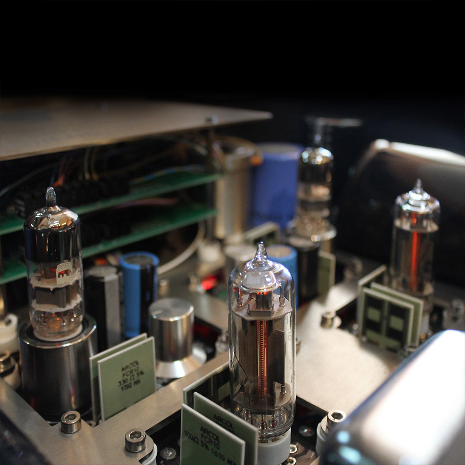
Inside an Inverted Triode tube, the electron stream emitted from a heated cathode is accelerated towards the anode, now a wire-grid-like structure. The electron flow is thus now unimpeded since no grid structure exists between the anode and cathode. Instead, a plate-like structure enveloping the cathode/anode assembly (called the control “grid”) is shadowing the anode electrical field, having a very high negative electrical field itself, thus “pushing” the electrons away from the anode.
This mode of electron flow control is completely different than a triode mode of operation.
The parameters of this new active element behave very differently than a conventional triode; the inverted triode actually acts like a virtual “vacuum state transformer”. Instead of having gain, the inverted triode has a gain that is a fraction of unity, just like a step down transformer. The internal resistance is many times lower, and input capacitance is nearly zero.
The extra-ordinary parameters of the inverted triode used (100 times lower plate resistance than a 6SN7 tube, zero input capacitance) gives the output stage unrivalled measured performance: 2Hz-500KHz bandwidth, figures unreached by any triode – transformer output stage.
An example of the Inverted Triode’s technical advantage over a typical vacuum tube, example the 300B, is a comparison of the two driving the same output transformer. The Inverted Triode tube presented a power bandwidth of 2Hz-500.000Hz where the 300B tube had a bandwidth of 15Hz-100.000Hz. Same transformer, same driver tube, but 5 times the bandwidth for the Inverted Triode tube.
The output stage is driven by the input tube with the help of an amorphous Double C-Core signal choke. The output stage is driving a highest quality Double C-Core output transformer, with bifilar winding techniques, which gives the transformer supreme frequency extension and supreme transient signal response parameters.
The Power Supply
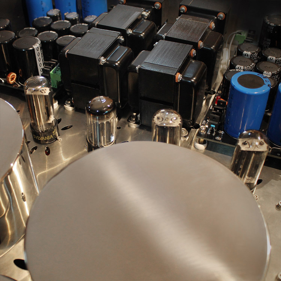
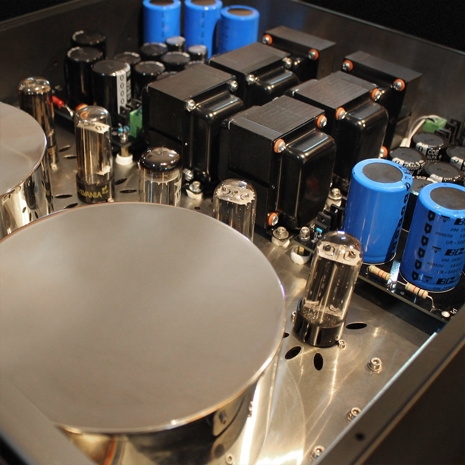
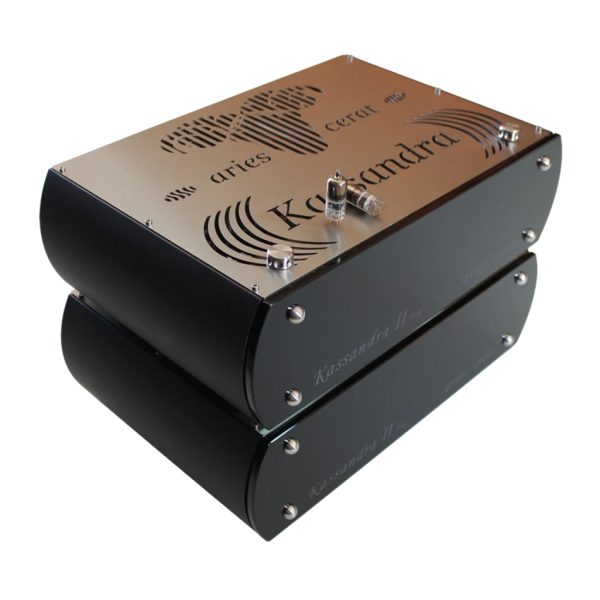
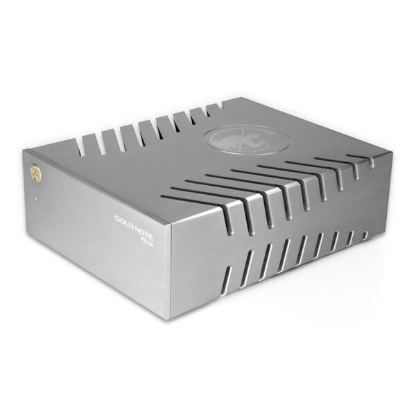
The power supply comes encased is a full sized chassis, and it is a true dual mono configured design, housed in a single chassis.
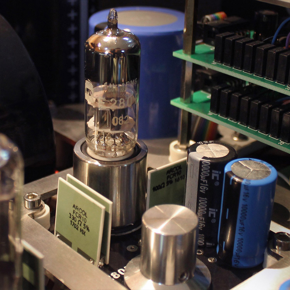
The driver stage is powered by a dual damper-diode-tube-rectified unit, one per channel. It is filtered further by dual choke PI filters, using low DRC inductors and high speed film capacitors.
The negative bias supply,is also using tube rectifiers , providing zero switching noise, and is also triple stage filtered, before feeding the driver stages.
The Inverted Triode stages, are also supplied by dual(one per channel) high energy PSU, again double filtered using low DCR inductors and high current/low ESR capacitors.
All stages are locally decoupled at the main unit. The driver stage is using two extremely low DCR custom film capacitors. These custom units present about 100 times less ESR than most electrolytic capacitors.
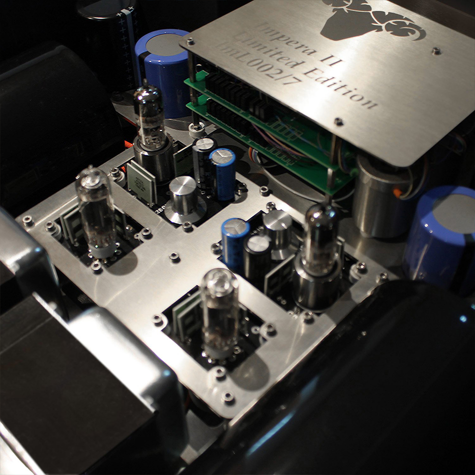
Signal attenuation in the Impera is achieved with a uniquely designed multi-tap input transformer, which has special bifilar winding as well, resulting in excellent performance both in frequency and time domain. The 26 separate taps are switched by small sealed signal relays.
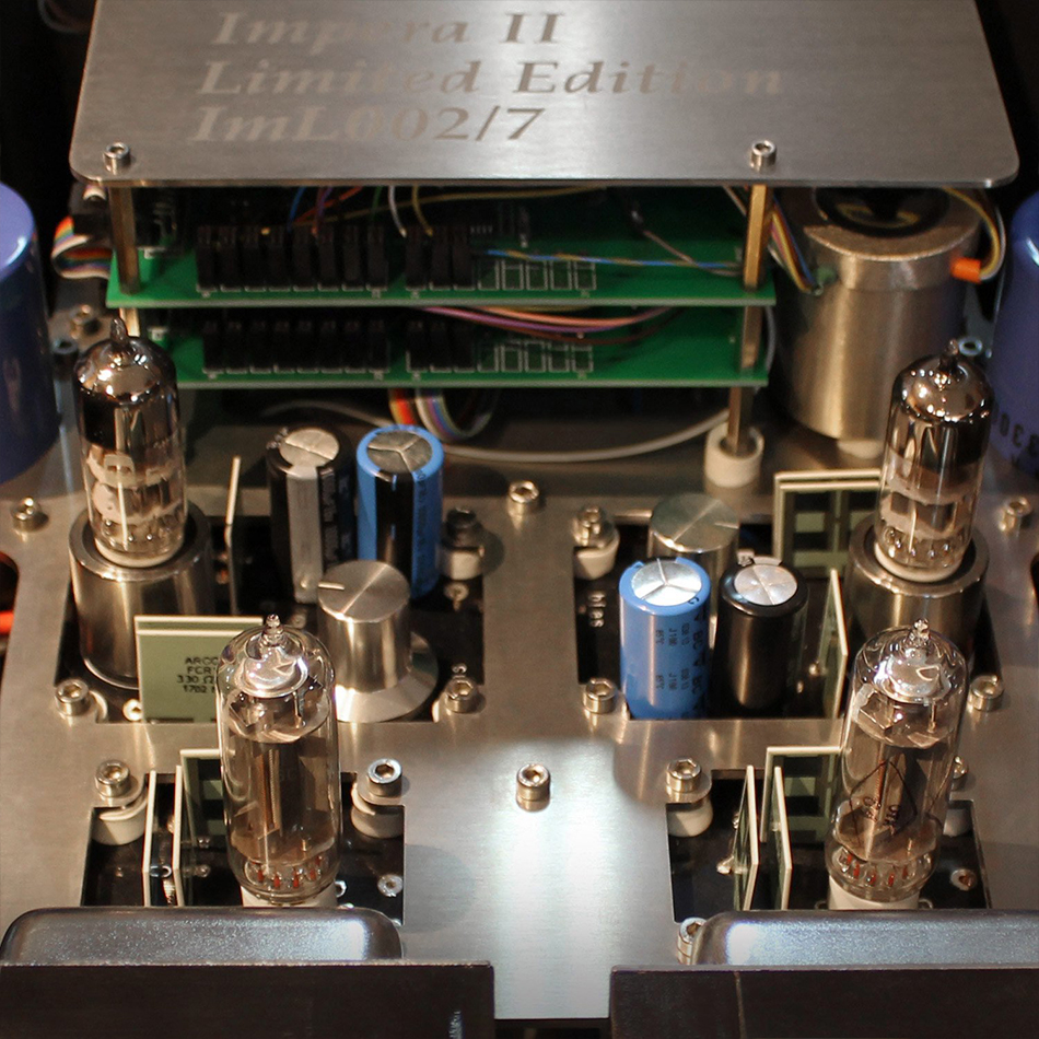
All four vacuum tubes are fed by special quality PSUs, with four individual choke filtered capacitor banks.
The sound or non-sound of the Impera II, is a brand new experience in the audio world, and is achieved by radical new solutions, created after out-of the box research and testing.
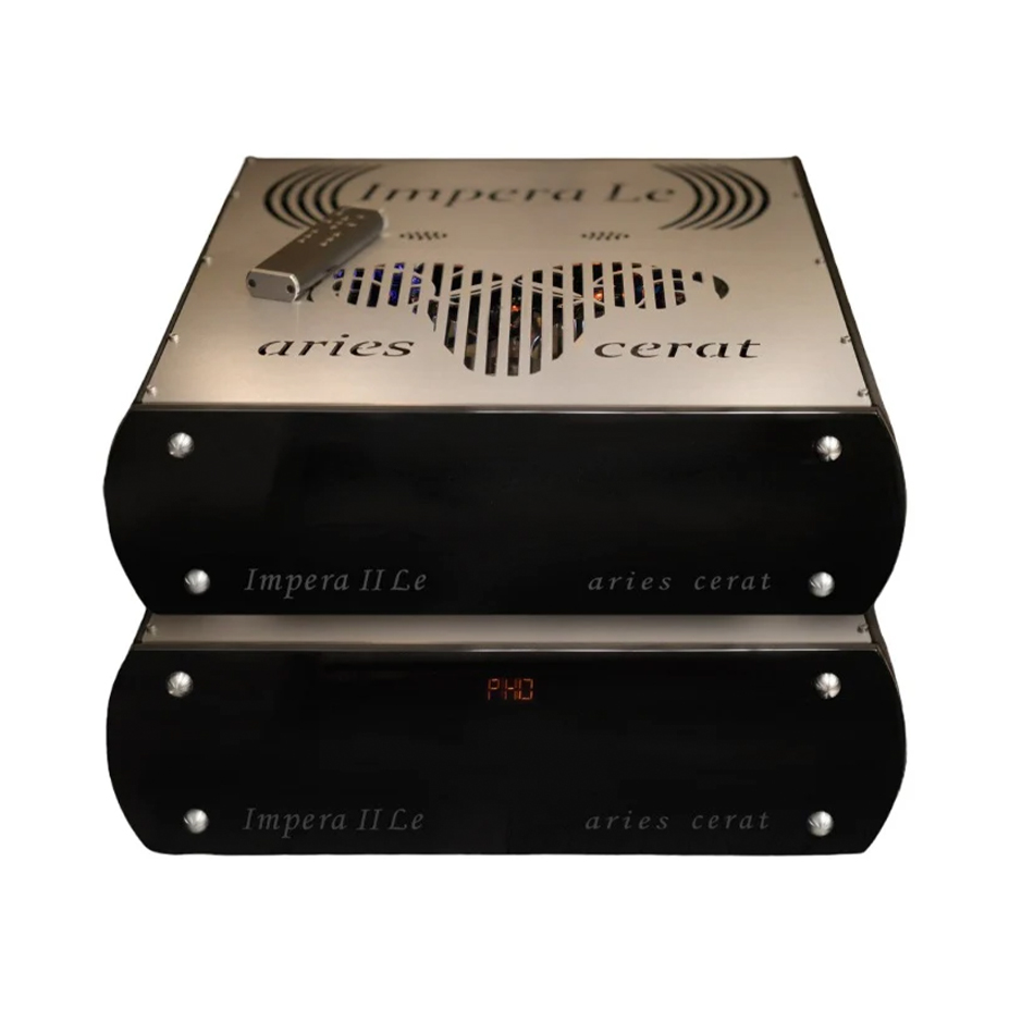
The Impera II Limited Edition is the second design in the Impera Series which will use our Gen 2 Inverted Triode technology.
Using all of our data and lessons learned in the 10 years researching and using the IT (Inverted Triode) technology, we took some steps into further improving the technology, both in measurable (objective) and sonic (subjective) aspects.
The main difference of the Gen 2 to Gen 1, is the use of dual IT(Inverted Triodes) in parallel mode, while working on very different operating conditions that Gen 1 IT. This further improved the distortion, noise and IM figures, while bandwidth almost doubled ,even if by using the same passive components( ex, the output transformer).
Moving the OP(operating point) to new ,previously unusable regions, allowed us to lower the grid (plate) consumption thus improving IT life as well. The Gen 2 technology also includes different biasing/driving circuits. The driving/bias stage is now a stacked/folded configuration, further improving bandwidth, stability and transient response. In short, the Gen 2 IT technology is a complete redesign and rethought process of the IT technology, which was time to get a step even further.
A quad of the trusted 6AU4 rectifiers feed the driver supplies, while the great sounding GZ34/5AR4 provides negative bias voltage to the sensitive circuits.










Reviews
There are no reviews yet.